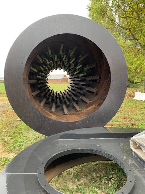
Cylinder Shell:
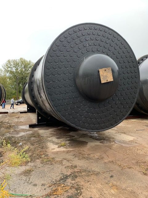
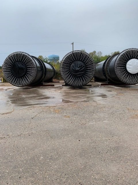
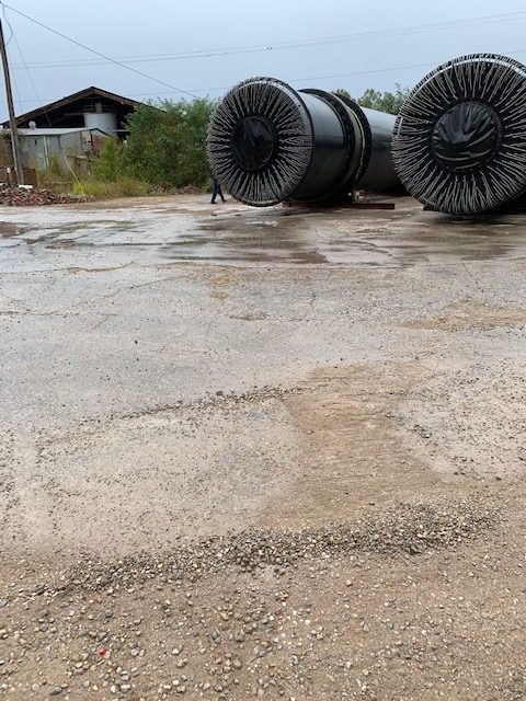
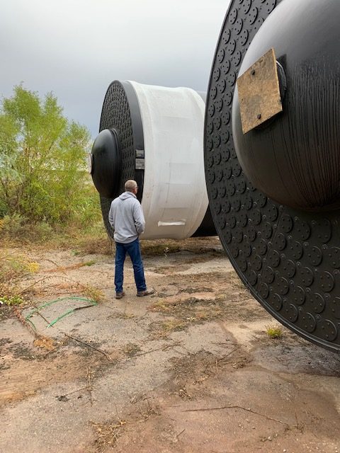
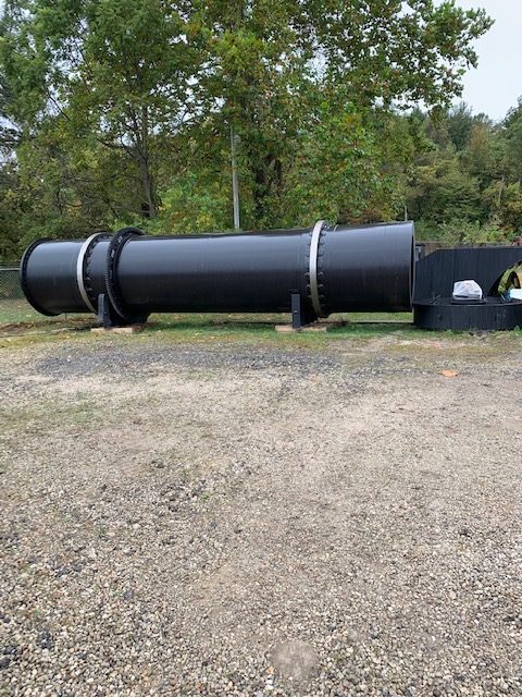
The shell is fabricated of 5/8” thick carbon steel plates with 1½” thick carbon steel heavy
sections under the tires and girth gear section.
Bar Flights:
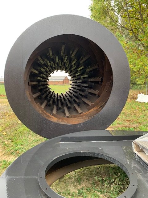
Bar flights are ¼” x 1½” equally spaced and extend the full length of the shell.
Steam Tubes:
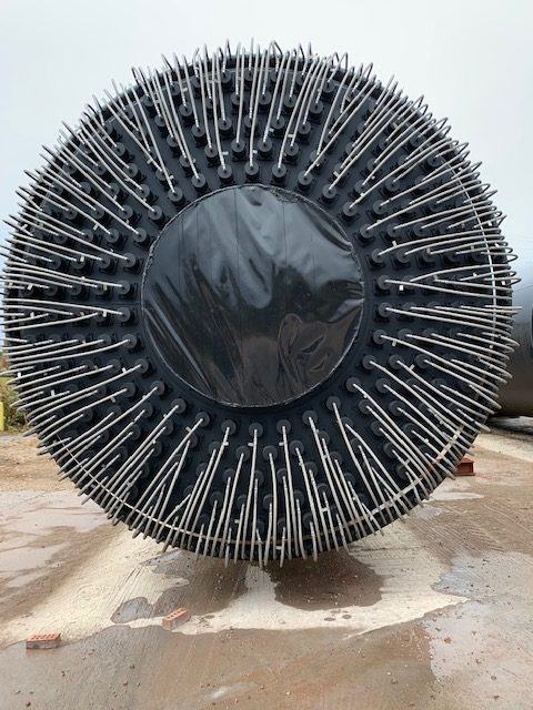
Quantity (210) 4” 11 ga carbon steel steam tubes. The tubes have been expanded and flared into the
manifold tube sheet
Intermediate Tube Supports:
The dryer shell has three (3) sets of tube supports. Each set consists of six (6)
segments using gussets designed to minimize shell stress concentration. The tube sleeves are 0.188” wall by 2”
long. This tube support design greatly reduces shell stresses.
Steam Manifold:
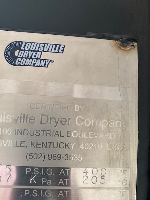
The manifold is designed, fabricated, tested and stamped to operate under a maximum allowable
working pressure of 150 PSIG steam service in accordance with the latest edition of the ASME pressure vessel code.
The tube sheet openings are double grooved for a positive seal. The manifold is manufactured from pressure vessel
quality SA-516-70 steel.
Fluehead:
The fluehead is 1” thick with tube holes which allow the end of the tube to penetrate the shell. The tubes
are sealed with carbon steel packing glands using packing or o-rings.
Vent Header:
The vent header ring is fabricated from 4” schedule 40 SA-53B pipe. Each steam tube is vented of
non-condensables by means of a flexible stainless steel braided-Teflon core hose with threaded ends. The header itself is vented by four (4) Spirax Sarco thermostatic vent valves.
Air Seals:
A Kevtex belt seal assembly is utilized on both, the feed housing/shell interface and the discharge
housing/shell interface.
Feed Assembly:
The feed assembly is carbon steel. The screw is a one-piece design. The feed assembly
incorporates a flanged sweep gas inlet port.
Discharge Housing:
The discharge housing is carbon steel construction that incorporates the discharge seals. A
flange is provided for connection to the customers vapor exhaust gas system.
Drive Components:
The dryer is driven by means of a girth and pinion gear with a:
– TEFC, 480 V motor with gear reducer.
– The pinion gear is mounted onto a jack shaft coupled to the reducer.
– Falk Steelflex T10 high speed coupling.
– Low speed coupling.
– SKF bearings to be provided.
Tires:
The tires are 4140 forged rings heat treated to 280-320 BHN. The tires are mounted on rolled filler bar
supports with allowance to accommodate thermal expansion of the shell.
Trunnion Base Assemblies:
Each tire rotates on “live shaft” type trunnions machined from AISI 4340 solid
forgings, with pillow block bearings. The pillow blocks, supporting the shafts, are mounted on top of a sub-frame.
Two (2) thrust roll and stand assemblies are positioned on one of the bases. The thrust rolls hold one of the two
dryer tires in a semi-fixed position, forcing the cooler shell to expand in directions away from that tire. As a safety
feature, the downhill or uphill thrust of the cooler is normally compensated for by “tracking” the dryer trunnion
rollers. This allows the tire to float back and forth between its two thrust assemblies. Graphite blocks are included
for tire lubrication.
Lubrication:
Tires, trunnions, and thrust rolls are lubricated by graphite block. Ring and pinion gear are
lubricated by oil drip system.
Rotary Steam Joint:
A Kadant Johnson Corp. Model 1050 ELS rotary steam joint with flex hoses is
provided.
Guards:
Pinch point guards provided for the tires and trunnions. The gear has a fully enclosed guard.
Painting:
All carbon steel, with the exception of machined surfaces, are painted using a high quality industrial
enamel coating system.
Hydro Testing:
Hydro testing was performed with standard city water.

